Reinforced soil walls have become one of the most widely adopted retaining solutions in modern civil engineering due to their structural efficiency, economic advantage, constructability, and seismic resilience. Among various reinforcement types, uniaxial geogrids are specifically engineered to resist horizontal earth pressures, making them the preferred reinforcement for retaining walls and steep reinforced slopes.
This article provides a comprehensive, engineering-focused explanation of uniaxial geogrid reinforced soil wall design, covering fundamental theory, design methodology, stability calculations, reinforcement layout, material selection, drainage design, construction control, and long-term performance considerations.
The content is written to align with international standards, practical design workflows, and real-world construction conditions.
1. Fundamentals of Reinforced Soil Wall Systems
A reinforced soil wall is a composite earth structure consisting of:
- Compacted granular backfill
- Tensile reinforcement layers (uniaxial geogrids)
- A facing system providing confinement and erosion protection
Unlike traditional rigid concrete retaining walls that rely solely on bending and mass, reinforced soil walls derive stability from the interaction between soil and reinforcement, forming a stable gravity block.
Why Reinforcement Works
Soil is strong in compression but weak in tension. Uniaxial geogrids:
- Take tensile forces generated by lateral earth pressure
- Restrict soil deformation
- Increase apparent shear strength of the reinforced mass
This mechanism allows reinforced soil walls to be:
- Taller
- More flexible
- More tolerant of differential settlement
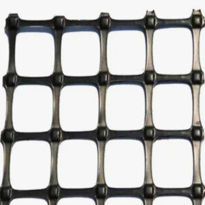
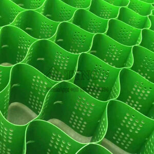
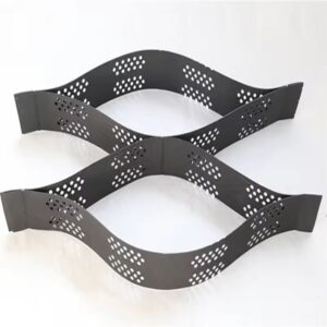
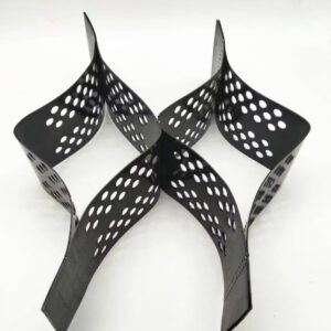
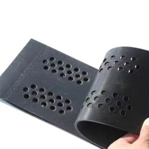
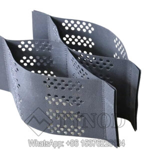
2. What Is a Uniaxial Geogrid and Why It Is Used for Walls
A uniaxial geogrid is a geosynthetic reinforcement with:
- High tensile strength in one principal direction
- Low elongation under sustained loads
- Minimal transverse strength
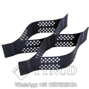
Structural Advantage in Wall Design
Earth pressure behind a retaining wall acts predominantly horizontally. Uniaxial geogrids align their machine direction perpendicular to the wall face, directly resisting this force.
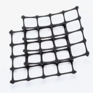
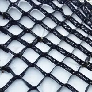
Compared with biaxial or triaxial geogrids:
- Uniaxial geogrids provide higher tensile capacity per unit cost in the required direction
- Long-term creep performance is superior for permanent structures
3. Typical Applications of Uniaxial Geogrid Reinforced Soil Walls
Uniaxial geogrid reinforced soil wall design is commonly applied in:
- Highway retaining walls
- Bridge abutments
- Railway embankments
- Industrial platforms
- Port and container yard walls
- Mountain road widening projects
Wall heights typically range from 3 m to more than 20 m, depending on soil conditions and reinforcement strength.
4. Design Standards and Reference Codes
Design must comply with recognized standards. Commonly used references include:
- AASHTO LRFD Bridge Design Specifications
- FHWA MSE Wall Design Manual
- BS 8006 (Code of Practice for Strengthened/Reinforced Soils)
- EN 14475 (European Standard)
While methodologies vary slightly, the design philosophy is consistent:
- External stability
- Internal stability
- Facing stability
- Global stability
5. Required Design Inputs
Accurate input parameters are critical for reliable uniaxial geogrid reinforced soil wall design.
5.1 Soil Properties
- Unit weight (γ)
- Internal friction angle (φ)
- Cohesion (usually conservatively taken as zero)
- Interface friction between soil and geogrid
5.2 Geometry and Loading
- Wall height (H)
- Wall face inclination
- Surcharge loads (traffic, structures)
- Seismic coefficients (if applicable)
5.3 Geogrid Properties
- Ultimate tensile strength
- Long-term design strength (LTDS)
- Reduction factors for:
- Creep
- Installation damage
- Environmental effects
6. External Stability Analysis
External stability treats the reinforced soil mass as a rigid gravity retaining block.
6.1 Sliding Stability
Sliding occurs when horizontal driving forces exceed base resistance.FSsliding=Paμ⋅W≥1.5
Where:
- μ = friction coefficient at base
- W = weight of reinforced soil block
- Pₐ = active earth pressure
Improvement measures:
- Increase reinforcement length
- Improve foundation soil
- Add shear key if necessary
6.2 Overturning Stability
Check resistance to rotation about the toe:FSoverturning=MoverturningMresisting≥2.0
Reinforced soil walls typically achieve stability through sufficient base width (0.6–0.7H).
6.3 Bearing Capacity
Foundation soil must safely support the reinforced mass.
Design checks include:
- Maximum bearing stress ≤ allowable bearing capacity
- Eccentricity e ≤ B/6
6.4 Global Stability
Global stability considers deep-seated slip surfaces passing beneath or behind the wall.
Methods:
- Limit equilibrium analysis
- Circular or composite slip surfaces
Minimum factor of safety:FSglobal≥1.3
7. Internal Stability Analysis
Internal stability governs the strength, spacing, and length of uniaxial geogrid layers.
8. Tensile Rupture Analysis
Each geogrid layer must resist tensile forces generated by earth pressure at its depth.Trequired=Ka⋅γ⋅z⋅Sv
Where:
- Kₐ = active earth pressure coefficient
- z = depth below wall top
- Sᵥ = vertical spacing
Design requirement:Tallowable≥Trequired
Only long-term design strength should be used, not ultimate strength.

9. Pullout Resistance and Anchorage Length
Adequate embedment beyond the failure plane is essential.
Pullout resistance depends on:
- Effective normal stress
- Interface friction
- Embedded length
Required factor of safety:FSpullout≥1.5
Typical reinforcement length:
- 0.7–0.8H for standard conditions
- Increased for poor backfill or heavy surcharge
10. Vertical Spacing of Uniaxial Geogrid
Vertical spacing directly affects wall deformation and facing stress.
Common Practice
- 0.4–0.6 m for tall or heavily loaded walls
- 0.6–0.8 m for standard walls
Smaller spacing:
- Improves stiffness
- Reduces facing movement
- Increases material cost
11. Facing Systems and Connection Design
Facing systems provide confinement and erosion protection, not primary structural resistance.
Common facing types:
- Segmental concrete blocks
- Precast concrete panels
- Wrapped-face systems
Connection strength must exceed the maximum tensile force in the geogrid layer with appropriate safety factors.
12. Drainage Design and Water Control
Water is one of the most critical factors affecting reinforced soil wall performance.
Drainage Components
- Free-draining granular backfill
- Drainage geocomposite or gravel zone
- Toe drain and outlet system
Poor drainage increases:
- Earth pressure
- Risk of instability
- Long-term deformation
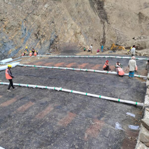
13. Construction Sequence and Quality Control
Even a perfect design can fail due to poor construction.
Recommended Construction Steps
- Foundation preparation
- Leveling pad installation
- Facing placement
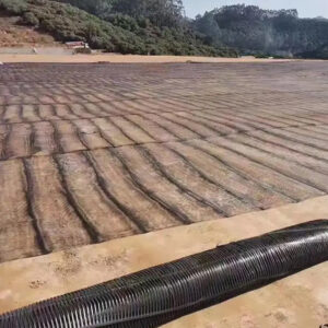
- Backfill placement and compaction
- Geogrid installation (correct orientation and tension)
- Repeat layer by layer
Compaction equipment must avoid direct contact damage to the geogrid.
14. Long-Term Performance and Durability
Uniaxial geogrids are designed for service lives exceeding 75–100 years when properly specified.
Key durability considerations:
- Creep behavior
- Chemical resistance
- UV exposure during construction
- Installation damage
15. Common Design and Construction Errors
- Using biaxial instead of uniaxial geogrid
- Insufficient reinforcement length
- Ignoring global stability
- Poor drainage detailing
- Inadequate backfill quality
Avoiding these errors is critical for long-term safety.
16. Advantages of Uniaxial Geogrid Reinforced Soil Wall Design
- Optimized tensile resistance direction
- Excellent creep resistance
- High load-carrying efficiency
- Flexibility under seismic loading
- Lower cost compared to rigid walls
17. Design Summary Table
| Parameter | Recommended Value |
|---|---|
| Reinforcement length | 0.7–0.8H |
| Vertical spacing | 0.4–0.8 m |
| Sliding FS | ≥ 1.5 |
| Overturning FS | ≥ 2.0 |
| Pullout FS | ≥ 1.5 |
| Global stability FS | ≥ 1.3 |
18. Conclusion
Uniaxial geogrid reinforced soil wall design is a proven, reliable, and cost-effective solution for modern retaining structures. When designed with proper consideration of external stability, internal stability, drainage, and construction control, these systems deliver outstanding long-term performance.
For engineers and project owners, the key to success lies in:
- Correct geogrid selection
- Adequate reinforcement length and spacing
- High-quality backfill
- Strict construction supervision
When these principles are followed, reinforced soil walls using uniaxial geogrids provide structural safety, durability, and economic efficiency unmatched by traditional retaining systems.